In Europe, connectors Type 2 (Type 2 Mennekes / IEC62196-2) for charging with AC current and CCS (Combined Charging System / IEC62196-3) for charging with DC, have gained dominance as the standard for vehicle charging connectors. These two connector types are used across nearly all manufacturers and follow the same operating principles regardless of vehicle brand or model.
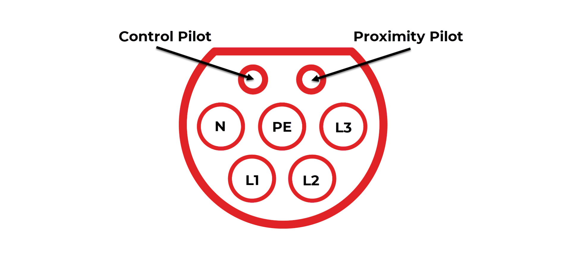
The Type 2 connector for AC charging has 7 contacts for 3 phase AC connection or 5 contacts for 1 phase. On the cable side (from the charging station) there is a male with sockets, while on the vehicle side there is a female with pins that have a plastic cap as protection against

The terminals are labeled Protective Earth (PE), N, L1, L2, L3, Proximity Pilot (PP), and Control Pilot(CP). The last two are mainly used in communication and charging management. In the basic state, the only active outlet is CP.
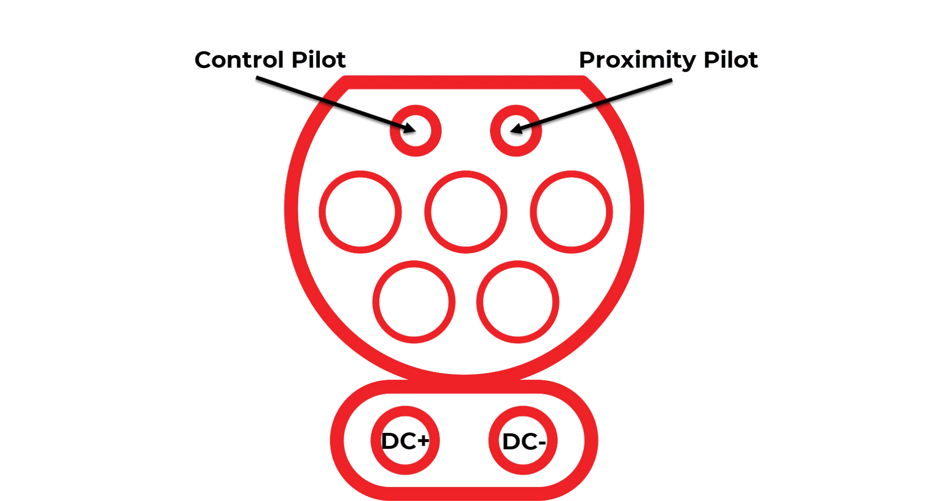
The Combined Charging System (CCS) connector is found at dedicated DC charging stations typically at fuel stations, or dedicated public charging infrastructure points. It utilises the same physical structure of the Type 2 Mennekes connector with the addition of two DC terminals at the lower portion of the connector. The Control Pilot and Proximity Pilot terminals operate on the same principles as the Mennekes type.

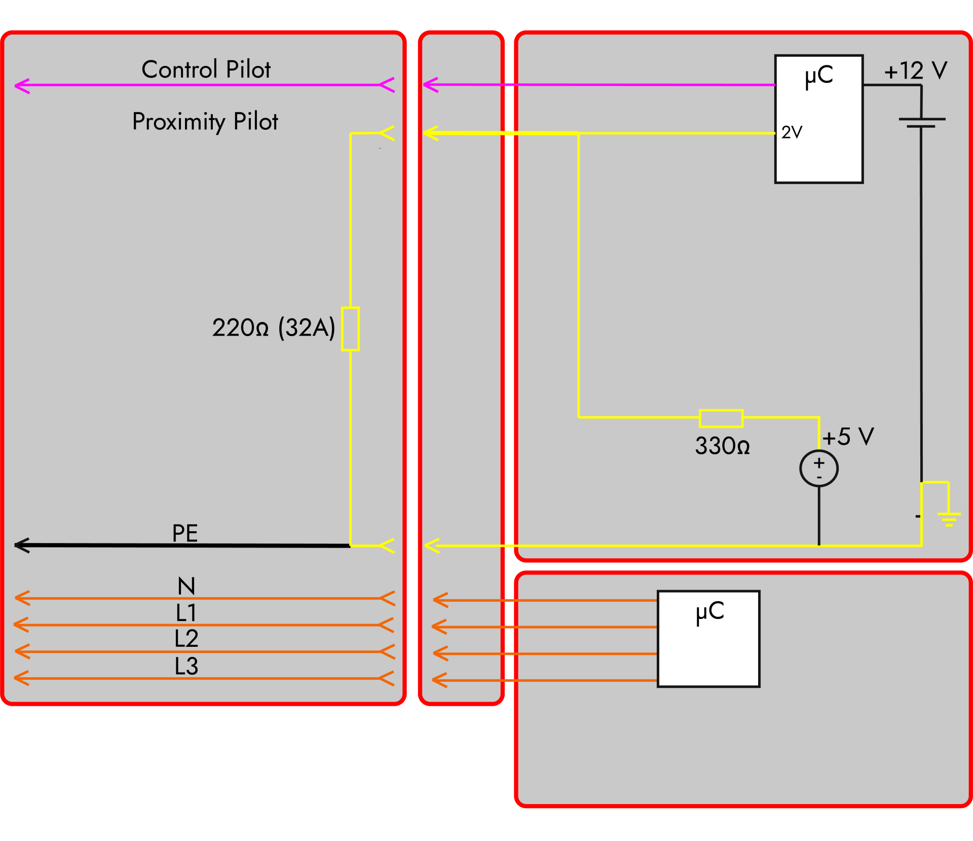
The Control Pilot terminal is physically shorter so that it is disconnected first, which ensures a safe shutdown of the voltage on L1, L2 and L3 or on DC+ and DC- during DC charging. This outlet is used to control charging. This connection is used by the charging station to transmit its capabilities, and the vehicle, on the other hand, its requirements. Connection is powered from the charging station, usually (during standby) +12 V DC through a 1 kΩ. resistor.
The Proximity Pilot is used to indicate a cable connection has been made, and confirm the current carrying capacity of wires and locking of connectors currently connected. The power for this circuit comes from the vehicle side (+5 V through a 330 Ω resistor) and the vehicle, among other things, uses it to communicate the request to unlock the charging cable, which gives the station time to turn off the voltage in a controlled and safe manner before disconnecting the circuit.
After connecting the charging connector to the vehicle, the voltage at the CP output will drop from 12 to 9 V, because the vehicle has a diode at the input followed by a 2.74 kΩ resistor to ground. The station detects this and responds with a 1 kHz and alternating (PWM) signal.
Similarly, the vehicle detects the connection of the charging cable and charging station via Proximity Pilot (PP) signal. At this moment, the vehicle disables its drivetrain and motors to prevent the cable from being pulled out. The station confirms locking by shorting a 330 Ω resistor on its side.
This is followed by the inclusion of another resistor in the CP circuit on the vehicle side, which signals the request to start charging. According to the value of the resistor and the voltage, the station determines whether ventilation is required (charging outside). If all conditions are met, your EV will start charging.
Since both control signals are measured against Protective Earth (PE), the disconnection of this protective conductor is easily recognizable. Communication is analogue and is relatively simple to implement and resistant to signal interferences and errors.


